Make Your Own GestureControlled Robot Circuit Diagram
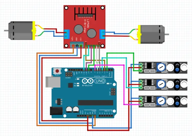
BlogMake Your Own GestureControlled Robot Circuit Diagram Depending on the values received from the IR module, the Arduino controls the two motors separately. Thus, making the robot turn left or right to avoid the obstacle. L293 MOTOR DRIVER: The driver has 2 inputs for power, 4 points for motor control inputs, and 4 points for motor control outputs. That is a set of 2 inputs and 2 outputs for each motor.
This circuit design features an Arduino UNO and a variety of motors and sensors to create an autonomous robot capable of navigating its environment while avoiding obstacles. Utilizing an ultrasonic sensor for distance measurement and a servo motor for directional control, the robot can make real-time decisions to move forward, backward, or turn

Adding Control with an Arduino for a Robot Arm Circuit Diagram
Robot Journals Robot Theory Conferences - THE $50 ROBOT - STEP-BY-STEP ROBOT TUTORIAL STEP 3b: CONSTRUCT THE CONTROLLER. Electronics, Continued Continuing from Step 3A, I will now show you the schematic we will use to build the circuit, followed by step-by-step instructions on how to wire your robot controller together.

Make Your First Arduino Robot - the Best Tutorial!: Smartphone controlled , obstacle avoiding and wall follower robot. "If you are not using the shield but using the l293d IC or module then visit my blog post's last section for the circuit and program." Hc-sro4 ultra sonic sensor - Buy here; Hc-05 bluetooth module - Buy here; 2 x Gear motor
Make Your First Arduino Robot Circuit Diagram
The robot will still operate, because all of the components chosen for the Teensy can operate on a lower voltage. However, the onboard regulator on the Teensy will ;be running unregulated. Optional Items. I want a way to control the board through my smart phone at some point, so I included a BLE device in the schematic. Insert 40-amp Circuit Breakers into the positions on the PDH corresponding with the Wago connectors the motor controllers are connected to. Note that the white graphic indicates which breakers are associated with which terminal pairs. If working on a Robot Quick Build, stop here and insert the board into the robot chassis before continuing.